Prototyping a trackball
The last couple weeks I’ve been playing around with prototyping a trackball. I’ve been babbling about it over on the fediverse and folks have asked for more details so here we are. The hope is that this will eventually be a more polished project, with a big fancy page and what not. But folks asked about this awful prototype phase and who am I to say no to publishing embarrassing work?
This started with the aball, an open source buttonless trackball. I tried to build one and… let’s just say it wasn’t for me. I have lots of opinions here but we can just move on. Come find me elsewhere if you want those opinions. The aball works and it works well for its creator, just not for me. Regardless, the aball was the launching point and got me spinning. This initial prototype was basically my attempt to do an aball-like thing on my own. (Also a shout-out to the Ploopy Nano Trackball for helping me develop additional opinions. If you want a commercial-ish aball, this is your ticket.)
Some goals are:
- Allow the controller to be easily replaced or upgraded. Pro Micro compatible controllers fit this really nicely. They are plentiful, relatively easy to come by, can be really cheap, and they can run QMK, an open source firmware with pointing device support. I have a lot of these laying around because I build keyboards. QMK’s built-in pointing device support will lessen my coding burden significantly
- Allow the sensor to be easily replaced or upgraded
- Easily accessible parts so you don’t need to be sungo with sungo’s workbench to build the thing
The Bill Of Materials
Let’s talk parts.
First, the really important bits:
- Pro Micro compatible controller. Any will do but I used a USB-C Pro Micro from Keyhive
- PMW3360 Motion Sensor from JACK Enterprises / Tindie
- Three 3x7x3mm deep group ball bearings
- 34mm trackball
And the connective bits:
- Adafruit Perma-Proto Small Mint Tin Size Breadboard PCB
- One PCB mount tactile switch
- Dupont Header for attaching the sensor
- For the MCU, I used machine pin headers because my keyboards use machine pins exclusively. Machine pins are not required though. use whatever makes you happy.
- For the sensor, use standard square male headers. This is actually important because machine pins won’t fit in the dupont connector.
- Four M3 screws and nuts for mounting the protoboard. I recommend nylon as I’ll discuss below.
- Four M2x6mm or M2x8mm screws to secure the lid. Use metal screws here.
- Three M3 screws with nuts to attach the bearings. I also recommend nylon as I’ll discuss below.
- Spools of wire. Dealer’s choice. I used 22AWG Solid Core
- Solder, soldering kit, etc. (If you don’t have this already, this build probably isn’t for you, to be honest)
The Build
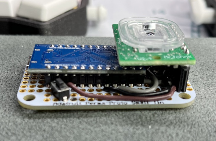
Here’s the end state we’re striving for. The MCU is mounted chips-down onto the machine pin headers. The sensor is attached to a dupont header on the end which holds the sensor pretty sturdily in place.
The Wiring
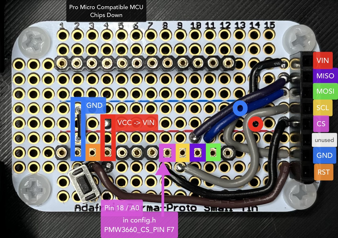
Forgive my messy wiring. The PCB is wired so that the dupont connector on the end matches up, pin wise, with the layout of the PMW3360 sensor breakout. The sensor’s layout is a bit wonky which makes wiring a bit of a mess. The image below shows the PCB from above with color coding matching the MCU header location and the destination on the dupont connector.
Sensor
Solder header pins on to the sensor with the pins sticking out the opposite side from the lens (see the first picture in this section). The holes are nicely staggered a bit and should hold the header nice and tight during soldering. Absolutely take off the lens before getting the iron anywhere near the sensor.
Firmware
At this point, it’s possible to test the build.
Flash the controller with QMK before plugging it into the PCB. This will ensure
that the board is good before maybe my bad instructions cause problems. Use the
handwired/aball keyboard, but only after applying this
patch. The patch switches the
aball to the PMW3360 sensor and ups the CPI (essentially the refresh rate) on
the sensor to its max. (This may be too sensitive for folks and it can be tuned
in config.h and set to a lower value.)
Fun fact, before we move on. The patch also inverts the X-axis. This stumped me for a bit before I realized this is a mouse sensor. It’s actually built to be upside down from my configuration. Flip it around and stick it in a rat-tail mouse and the X axis is totally fine. For this use case, we have to invert it.
Also, the CS pin choice is totally arbitrary. The aball uses F7 and I carried
that over. If you want to use some other pin, go to town and set
PMW3360_CS_PIN appropriately in config.h
Once you’ve successfully flashed the firmware, unplug the controller and smoosh all the parts together. Plug it into a computer and move your finger slowly above the sensor, about 3mm or so. If all is working, you’ll see the mouse move around the screen a bit.
The Case
Once you’ve got tested and functional circuitry, it’s time to build the case. There are two STL files you’ll need to print off. Neither requires supports or rafts or any of that jazz. Infill and perimeters are dealer’s choice; there’s no unusual requirements for strength and PLA works just fine.
Draw The Rest Of The Owl
Screw everything together.
Put M3 nylon screws through the corners of the protoboard and out the bottom, attaching nuts there. I recommend nylon because it’s non-conductive, won’t interfere with any of the solder bridges, and you can cut them flush to the nut on the bottom if you want.
Because it’s impossible to center the MCU on the perma-proto board, the USB adapter will not center on the opening. I’ve made the opening pretty wide though and all my gigantic USB-C connectors work fine with my MCU.
While not required, I recommend putting bump-ons on the bottom corners to help the trackball stay still and give plenty of room for the nylon nuts. These 4mm bumpons from Amazon work great.
If all went well in the printing and build, the sensor should line up perfectly inside the square opening in the lid. If not, tracking will probably be inconsistent and weird.
Screw on the lid with the metal M3 screws. Use a powered screwdriver with decent torque because these screws will be held in place by melting the plastic during the insertion.
Attach The Bearings
The lid features three attachment points for the bearings. Slide an M3 nylon screw through the hole; slide the bearing onto the screw; secure it with a nut. I recommend nylon here because the bearing might try to rotate around the screw. If so, metal rubbing on nylon is a much better sound, and better on the bearing, than metal on metal.
Drop the trackball into the opening and roll it around to make sure you get clean rotation. It’s possible the bearings might not visibly rotate, depending on the weight of the trackball and the amount of pressure you apply while moving it. That’s perfectly fine and doesn’t affect operation.
The End Result
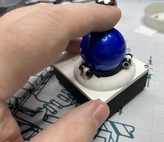
And here we are (so smol). It is important to note that the MCU sticks out to the left, not up. Yeah it’s weird. It’ll get fixed in a later build. At this point though, you should have a functioning, buttonless, trackball. At the very least, I do.
Future Direction
Like I said above, this is hopefully going to end up as more of a polished project with probably a custom PCB and buttons and other fun stuff. I’m currently iterating through ball mounts while pondering buttons. There’s also firmware work to be done, etc etc. Lots of work to do. If you have questions or comments, feel free to hit me up on the fediverse or email, using links in the footer.